Can a permanent magnet 24v flow motor be connected to an inverter
How an Inverter Drive Works and Controls the Speed of an AC Induction Motor
An Inverter Drive (VFD) works by taking AC mains (single or three phase) and first rectifying it into DC, the DC is usually smoothed with Capacitors and often a DC choke before it is connected

Operating Limits of Inverter-Driven Permanent Magnet Motor Drives
Experimental results are presented for two motors of different design, each using neodymium magnets and each supplied from a current-controlled inverter with hysteresis control of current
6 FAQs about [Can a permanent magnet 24v flow motor be connected to an inverter ]
What is a permanent magnet synchronous motor?
In PMSM and BLDCM, the rotor is made of permanent magnets such as neodymium-iron-boron alloy (NdFeB) and thus avoids rotor field winding. The interior permanent magnet synchronous motor supplied by a six-step inverter with electronic commutation is used as variable speed drive in pumps and fans .
What are permanent magnet brushless DC motors used for?
Permanent magnet brushless DC motors are used in laser printers, hard disc drives and electric vehicles [2, 27]. Electronic switching of the six-step inverter is controlled by the rotor position which is sensed by using either the optical or the Hall effect sensors [2, 3, 4, 5].
How do inverter motors work?
These motors are inverter driven and require sensing of rotor position information to generate gate pulse for the inverter to rotate the rotor in the forward direction. The sensing of rotor position can be using sensors which work on Hall effect, phototransistors and disc encoders.
How does a permanent magnet synchronous machine work?
The three-phase output voltage of this inverter is fed to the Permanent Magnet Synchronous Machine model from specialised technology block set. To this machine model, an external step load of 0.5 Nw-M for the first 2 seconds and 0.25 Nw-M for the remaining time is applied. Machine parameters shown in Table 7.2 are used.
What is the rotor speed of SVPWM inverter?
The mean rotor speed is 52.2 mech rad/sec which is very close to the set point speed of 54.140 mech rad/sec. The steady state stator current in Fig. 7.20 is close to 0.99 amps as recorded in Table 7.4. Also from Fig. 7.21, the line to line output voltage of three-phase SVPWM inverter is 24.14 volts (RMS) and the frequency is 16.824 Hz.
What is the line to line output voltage of SVPWM inverter?
Also from Fig. 7.21, the line to line output voltage of three-phase SVPWM inverter is 24.14 volts (RMS) and the frequency is 16.824 Hz. Converting the rotor set point speed of 54.140 mech rad/sec to electrical frequency, this value is 17.233 Hz which closely agrees with the frequency of the line to line output voltage of inverter.
More information
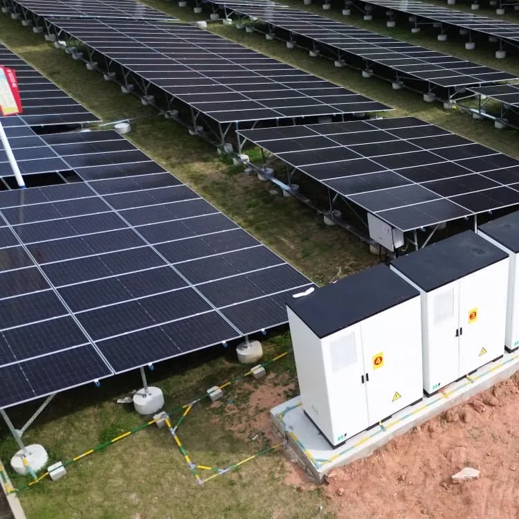
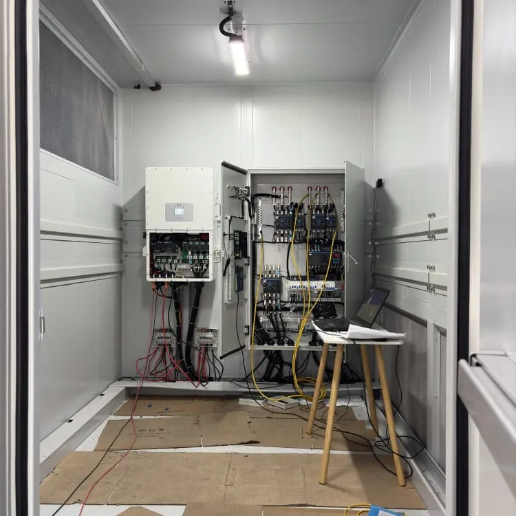
- Grid-side energy storage cabinet structure
- Solar 30W Variable Frequency Water Pump Inverter
- Battery cabinet size customization
- Lead-carbon battery energy storage life
- Equatorial Guinea Power Station Energy Storage
- Mali solar base station lithium-ion battery hybrid power supply
- US version outdoor power supply
- 18-cell battery cabinet ESS power base station
- Burundi outdoor battery mobile power supply
- The largest company in flow battery energy storage
- Inverter three-phase 5KW
- Advantages of energy storage products
- What are the outdoor power supplies that can produce 2 kWh of electricity
- The output voltage of the inverter of dozens of yuan
- New energy storage power supply
- What brand of Norwegian lithium battery pack is good
- Hybrid Solar Photovoltaic Power Generation System
- Zimbabwe Peak Valley Energy Storage Power Station
- Greek PV combiner box supplier
- Foreign trade energy storage power supply customization
- How many volts of electricity can a solar power station store
- Huawei Venezuela Energy Storage Cabinet Battery
- 2025 New Energy Storage Project
- Austria Performance Energy Storage Battery Company
- Photovoltaic inverter can
- 500v DC to AC inverter